LDR Manual
1. Volume control with LDRs
This section introduces the Light Dependent Resistor (LDR), provides a brief tutorial on how volume control works generally, and how volume control with LDRs is similar yet uniquely different from conventional volume control technology.
1.1. What is an LDR?
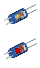
A light dependent resistor (LDR) is the marriage of a photoresistor with a light emitting diode (LED) in a small sealed package approximately the size of an M&M candy. Each LDR has 2 pairs of wires. One pair connects to the LED end while the second pair connect to the photoresistor end.
Inside the LDR, the LED shines light on the phtoresistor. The resistance of an LDR varies inversely in proportion to the brightness of the LED with brightness determined by the control current running through the LED. Increasing LED current increases the LED brightness which in turn reduces the the photoresistor resistance.
Through precise control of its LED current, LDRs can smoothly regulate resistance over a wide enough range to provide effective high performance audio volume control.
LDRs optically isolate the control circuitry from the audio signal passing through the photoresistor. The audio signal only encounters a variable resistance that is regulated by photons (i.e. light) and not electrons.
Tortuga Audio preamps utilize LDRs to control volume (i.e. to attenuate the audio signal).
1.2. Why LDRs for volume control?
We use LDRs because their subjective sound quality is amazing. Adjectives like clear, open, unveiled, organic, articulate, and uncolored all apply to the LDR. All while maintaining excellent bass and overall dynamics even in a passive preamp.
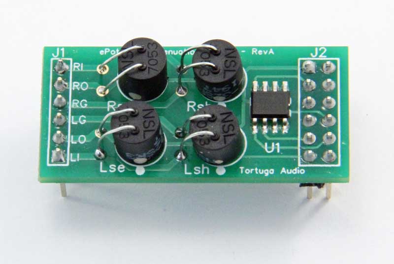
Figure 2. V3/V4 type module
|
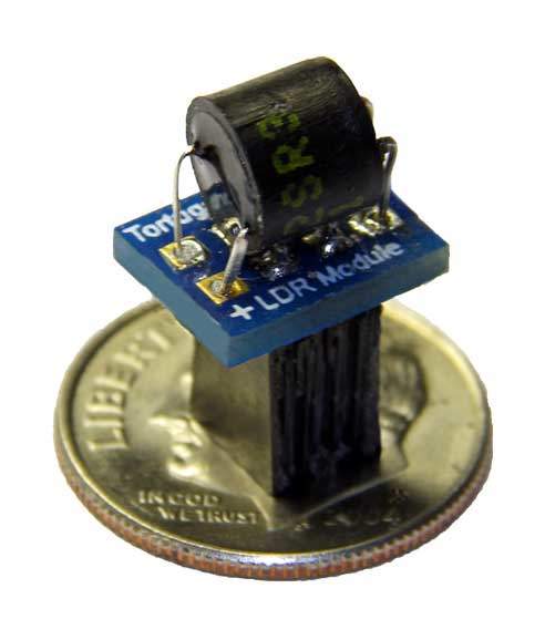
Figure 3. V2/V25 type module
|
If LDRs are so great why then why don’t all preamps use LDRs? A reasonable question with several answers.
First, LDRs are notoriously difficult to use for volume control. They are inherently nonlinear which means they are difficult to control accurately over the wide range of resistance needed for effective volume control.
Secondly, the performance curve of individual LDRs are not consistent even within the same make and model from the same production batch. Moreover, their performance curves may even drift slightly over time.
Last but not least, LDRs have higher distortion characteristics than most other alternatives although not enough that it really matters subjectively (the distortion is well below human detectable levels).
For all the above reasons most audio designers avoid taking on the challenge of using LDRs. That is not an irrational view.
Tortuga Audio took on this challenge over 15 years ago and has not looked back. We overcame these technical challenges. We are now on our 5th generation LDR preamp control technology.
1.3. Volume control is attenuation
When engineers talk about volume control they use the term "attenuation". Attenuation is the opposite of amplification. When you amplify an audio signal you are increasing its average voltage level. A higher voltage audio signal will be louder relative to a lower voltage signal. On the other hand, when you attenuate an audio signal you are reducing its average voltage level.
Attenuating an audio signal is typically done using a voltage divider. A potentiometer (a "pot") is the most common type of voltage divider. Almost every time you turn a volume control knob, you are turning a voltage divider pot. But not when you’re using a Tortuga Audio preamp!
1.4. How does volume control work
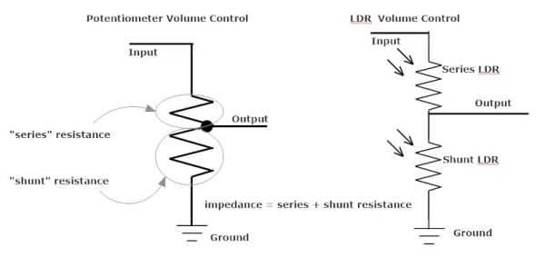
The figure above shows two different voltage dividers. On the left there’s a potentiometer and on the right is a pair of LDRs configured as a voltage divider. You’ll note there are obvious similarities between the two, at least schematically.
In both examples you have an Input signal feeding into a series resistor, followed by a shunt resitor connected to ground. The Output signal is the offtake point between the series and shunt resistors.
With a conventional potentiometer, the series and shunt resistors are a single continuous resistor material with a "wiper" output defining the split between the upper series resistance and the lower shunt resistance. As the user turns the shaft of the potentiometer, the wiper physically moves across the resistance material.
With an LDR voltage divider, the series and shunt resistors are in fact each a separate discrete LDR. The Output point is always between the two LDRs. Each LDR is controlled to achieve a specific resistance level.
The governing equations of most volume control are shown below
Let’s say you have an Rseries = 5k ohms and an Rshunt = 45k ohms. That yields an effective impedance of 50k ohms as seen by any device connected to the input of the attenuator. That gives us a ratio = 45 / ( 1 + 45) = 0.9. Plugging that into our attenuation formula we get dB = 20 x log (0.9) = -2.1 dB which would yield a modest level of attenuation that would be quite loud as a practical matter.
1.5. How do LDRs control volume?
Volume control with LDRs works basically the same as a potentiometer except that with LDRs the RSeries and RShunt resistance levels are controlled independent of each other. Once the LDRs are calibrated, a microcontroller controls each LDR to achieve the resistance ratios that correspond to the current target dB attenuation. While a pot does this mechanically, the resistance levels of both the series and shunt LDRs is done electronically with no mechanical wear parts.
Repeatable and reliable electronic control of LDRs is at the core of Tortuga Audio’s LDR volume control technology.
2. Adjustable impedance with LDRs
Tortuga Audio introduced adjustable impedance to its LDR preamp controller/attenuators in early 2015 as an optional feature. Tortuga Audio makes no claims guaranteeing the outcome of changing the controller’s impedance level. This feature is being provided solely as an exploratory option for those curious and wishing to explore possible outcomes.
Adjustable inpt impedance is not a common feature in audio equipment. Most audio equipment has a fixed input impedance that was established by the audio designer. Tortuga Audio’s LDR based preamp controller/attenuators are unique in this regard.
Adjustable impedance allows the user to configure up to 10 different input impedance settings each with its own defined impedance level between 1K and 99k. Impedance setting #1 is fixed at 50k and cannot be modified. Settings #2 through #10 are initially disabled and are entirely optional and can be ignored.
Once two or more impedance settings are properly configured, the user may switch instantaneously between different input impedance levels while playing music or running test signals. The user is free to explore and possibly fine tune their preamp’s impedance level to find an optimal level for their source(s) and amplifier.
2.1. Input & output impedance & why it matter?
Impedance is another word for resistance and is usually expressed in units of "ohms". In audio, impedance often involves complex relationships between simple fixed resistance plus dynamic resistance from capacitors and inductors that vary with the frequency of the audio signal. Impedance is also another way of talking about how hard audio equipment has to work to do its job. And the harder you have to work, the harder it is to be good at your job!
Impedance of a typical volume control voltage divider is shown in the figure above as the mathematical sum of the "series" and "shunt" resistance. Most volume controllers are in the range of 10k-100k ohms. Tortuga Audio typically sets the default input impedance of its LDR volume controllers in the 20-50k range.
Audio equipment typically has both an input and an output impedance.
Input impedance tells us how hard we have to work to get a signal into a device. Devices with high input impedance place minimal current demands on connected upstream components. This is good thing and usually translates into a better sounding system because the equipment pushing the audio signal doesn’t have to work as hard.
Output impedance tells us how the output audio signal holds up under load wherein a lower output impedance is almost always better.
A device with low output impedance is like a strong, steady water main that delivers constant full pressure regardless of whatever you connect to it. The signal arrives at the next component at the intended volume and with the intended sound, regardless of what that component is or how long the cable is.
Conversely, a device with high output impedance is more like a garden hose fed by a weak pump. A weak pump struggles to maintain pressure (voltage) as flow (current) increases. Plug it into one amplifier and it sounds fine. Plug it into another and the volume drops, the treble softens, or the bass gets flabby. Long cables make the problem worse, because a weak source cannot push high frequencies through them cleanly. The essential point is this: low output impedance means the device’s sound does not change based on what you plug it into.
Input vs. output impedance
The relationship between input and output impedance are inextricably linked by physics. While most volume controllers have a fixed input impedance, output impedance is typically not fixed but is instead dependent on the input impedance and the attenuation level.
Let’s unpack this by taking a closer look at the figure below that shows the relationship between impedance and the attenuation level of one of our earlier LDR3x.V2 LDR attenuators. This attenuator has 70 volume steps over a 60 dB range with a 20k nominal input impedance.
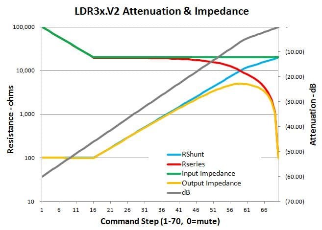
- dB schedule (black line)
-
The dB schedule is the attenuation schedule. This is our defined goal. All the rest falls out from this schedule. This particular example is a linear fixed dB per volume step except for a reduction in the schedule slope to lessen the incremental sound pressure changes as you approach full volume.
- Input impedance (green line)
-
The green line shows the input impedance as volume is adjusted between step 1 (minimum volume) and step 70 (maximum volume). Note the fact that the impedance doesn’t actually remain fixed at 20k but ramps up to 100k as the command step falls below 15. This is an artifact of the math of attenuation plus the limitations of LDRs. Simply put, we can’t maintain a fixed input impedance of 20k with a 60 dB control range. Doing so would require us to operate outside of the acceptable LDR window of minimum 100 ohms and maximum 100k ohms. To live within these constraints we allow the impedance to increase from 20k to 100k when volume is low. In practice, this has no discernible impact on the sound quality.
- RSeries (red line) & RShunt (blue line)
-
Recall that by definition, the sum of RSeries and RShunt is equal to the input impedance which is to say the green line equals the sum of the red line and the blue line. The LDR resistance schedule for RSeries and RShunt is derived from governing voltage divider equations that are not covered here.
- Output impedance (yellow line)
-
The yellow output impedance curve is by far the more interesting and non-intuitive of the these curves. Starting at minimum volume, note how output impedance is at its lowest and remains unchanged as input impedance falls from 100k to the target 20k. Once the input impedance reaches 20k, the output impedance climbs in sync with the increasing volume. But as the RSeries begins to drop quickly towards full volume, the output impedance hits a peak at -6 dB and then drops very rapidly reaching the same low level at both ends of the volume control range.
Output impedance - a deeper dive
The fact that most volume control devices do not have a fixed output impedance has real-world implications that are worth noting for those interested in understanding this topic more fully. Here are some additional points to consider regarding non-constant output impedance.
- Observations
-
-
Typical volume controls do not have a fixed output impedance
-
Output impedance changes every time you turn the knob
-
At full volume and at full mute, an output signal pushes easily through when impedance is minimal
-
Output signal weakens as the volume increases into the middle of its range
-
Output is weakest (impedance highest) around 6 dB below full volume, which is a fairly loud setting
-
- Why it matters
-
-
Sound can change with volume - Because the control’s ability to drive the next component varies with the setting, the tonal balance and the sense of dynamics can subtly shift as you adjust the volume. A system that sounds right at one level may sound a little softer or duller at another.
-
Outcome depends on connected equipment - A passive volume control relies on current drive of its source, the input impedance of the amplifier, and the length and quality of cables to the amplifier. Any or all of these can show up as lost treble, flabby bass, or reduced volume.
-
Higher impedance volume controllers are more affected. While increasing input resistance is gentle on the source feeding it, the price for doing so is a proportionally higher worst-case output impedance. Choosing a design impedance value is always a compromise between being easy on the source and being strong enough to drive the attached power amp with authority.
-
- How active beats passive
-
-
Performance independent of attached equipment - Conventional active preamp performance is rarely dependent on the impedance of attached upstream or downstream equipment.
-
Performance independent of volume level - Input and output impedances remain fix and optimal so the system sounds the same no matter where the volume knob sits.
-
- How passive beats active
-
-
A well matched passive attenuator operating between a robust low impedance source and a high impedance power amplifier, will have excellent performance, be dead black quiet between the notes, and lack nothing in tone or dynamics compared to any active preamp regardless of price.
-
2.2. Why change input impedance?
Conventional audio preamps have a fixed input impedance, chosen by the designer as a compromise. One of the benefits of using LDRs in lieu of fixed resistors or potentiometers is the ability to adjust the overall input impedance of the LDR attenuator. This is done entirely within the software and requires no additional hardware.
Adjustable input impedance lets the user resolve that compromise for their own system. The benefits fall into the following categories:
-
Matching the source - Every source component has its own output impedance and its own preference for how heavily it is loaded. Tube outputs, some DACs, and phono stages have relatively high output impedance and want a light load, meaning a high preamp input impedance, or they lose level and bass. Many solid-state sources are happy driving a heavier load and can sound more dynamic doing so. An adjustable input lets you give each source what it wants instead of hoping the fixed value is close enough.
-
Better current drive to the amplifier - As we discussed earlier, the input and output impedance are unavoidably linked in a passive volume control. The attenuator’s worst-case output impedance is a fixed fraction of its total resistance, so lowering the input impedance also lowers the output impedance. That makes the preamp stronger at pushing the signal through cables into the power amp, which preserves treble and dynamics. Adjustability lets you trade a little source loading for better amplifier drive, or the reverse, depending on which side of the system is more sensitive.
-
Lower noise - Lower impedance circuits generate less thermal noise and are less prone to picking up hum and radio interference. If the source can tolerate a heavier load, dropping the input impedance quiets the system.
-
Compatibility with multiple sources - A listener with several sources, or one who changes equipment over time, does not have to accept a setting that suits one component and compromises another. The preamp adapts rather than forcing a new purchase.
-
Tuning by ear - Because the ideal impedance value depends on the specific combination of source, cables, and amplifier, no designer can know the optimal impedance in advance.
| Making input impedance adjustable turns impedance from a hidden fixed spec into a control the listener can use to find the best sound for their system. |
2.3. Adjusting input impedance
Impedance setting #1 is fixed at a default level in all Tortuga Audio preamps; typically 50k but may also be 75-80k in some units. All Tortuga Audio preamps are shipped with a default input impedance at setting #1. The default impedance level at setting #1 can not be changed.
The user may configure up to 9 additional impedance settings #2 through #10 each with its own impedance level between 1k and 99k. Older preamps allowed for up to 5 different impedance settings (#1 plus 4 additional). This was later increased to 10 including the default setting #1 plus 9 additional.
Once one or more additional impedance settings have been properly configured and initialized, the user is then able to instantaneously switch back and forth between impedance levels while listening to music. This flexibility allows the user determine which input impedance level is optimal for a given system.
It’s important to remember that each new impedance setting/level requires the preamp to be run through at least 1 cycle of calibration in order to establish a new attenuation table at the new impedance level. A second calibration pass is highly recommended for newly established levels. Calibration must be run for each setting/level individually since calibration only operates on the currently selected setting/level.
Please consult the preamp controls section for detailed instructions on setting up impedance settings, adjusting impedance levels, and running calibration to generate a new attenuation table.
2.4. Switching between impedance settings
Once 2 or more impedance settings have been set up, you can switch between them in real time while listening to music or pushing through test signals.
Please note that if you switch to an impedance setting that is not defined, the audio output will shut off because there is no defined attenuation table. Switching back to a defined setting/level will switch the music back on.
You may or may not notice a qualitative difference between different impedance levels. Much depends on the specific equipment in your system.
Based on customer feedback and our own experience with adjustable impedance the optimal setting is one that provides sufficient impedance bridging (ratio of amp input impedance to source output impedance) between the source and the amp. Increasing the impedance bridging ratio further usually does not provide additional benefit and may in some cases actually have a negative impact on sound quality.
2.5. Please be patient and deliberate
Exploring adjustable impedance is something you should only do deliberately and with a patient attitude. Configuring a new setting for the first time or changing an existing impedance level can be a bit confusing and the process and procedures may not seem intuitively easy. A careful read of this information on adjustable input impedance, together with information on LDR calibration and the related preamp controls is highly recommended.
3. LDR calibration
3.1. Calibration in brief
Calibration is a self-contained measurement system that measures and records the resistance of each LDR against a 100-step attenuation schedule. The control command needed to achieve each targeted resistance step gets stored in permanent memory and subsequently used to set the resistance level of each LDR during normal operation.
-
Built-in software driven process
-
Normalizes LDR performance without need for pre-matched LDRs
-
Requires no special or external equipment
-
Only runs when preamp is otherwise offline and not operating normally
-
Once started runs automatically without any user intervention
-
Corrects for any drift as LDRs age
-
Allows LDRs to be replaced if needed thus extending the life of the pramp indefinitely
3.2. Why is LDR calibration a thing?
Using LDRs for audio volume control is technically challenging because the relationship between control current and resistance within each LDRs is highly nonlinear, can vary considerably from one individual LDR to the next, and can also change over time as an LDR ages. This nonlinearity is clearly evident in the resistance versus control current shown in the graph below.
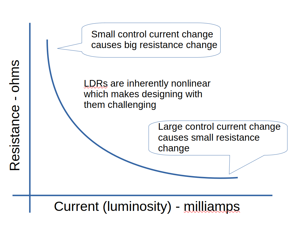
Figure 6. Typical nonlinear LDR behavior
|
The conventional approach to overcoming these LDR challenges is to measure hundreds of LDRs to find sets of matching pairs. However, even when initially matched, LDR behavior can change as they normally age. This can degrade the stereo imaging and sound stage over time and allow channel balance to drift left or right. Moreover, if one of the matched LDRs fails, the preamp might be rendered unusable.
Tortuga Audio introduced in-situ LDR calibration in May, 2014 with the release of its V2 preamp controller. Built-in "auto" calibration of LDRs eliminated the need for testing and matching LDRs. Moreover, it allowed LDRs to be mounted in plug-in modules that are easily replaced should an LDR ever go bad. In-situe LDR calibration is a unique feature of Tortuga Audio preamps.
3.3. What happens during calibration?
During calibration, four LDRs are each run through 100 calibration steps resulting in 400 total steps for a full calibration cycle that typically lasts for 10-15 minutes. If a calibration cycle hasn’t finished after 20 minutes, there’s probably a problem with at least 1 of the 4 LDRs.
During each calibration step, the resistance of the LDR is measured and compared to a target value. The target values are dependent on the specific input impedance value that the preamp is currently set at. If the input impedance is subsequently changed to a new value, calibration must be run again to build a new calibration table.
The control settings for each step of each LDR are stored in the controller’s EEPROM memory. These stored control settings are subsequently read from memory during normal operation and are used to set the resistance level of the LDRs (2 LDRs per stereo channel) to achieve the desired volume.
3.4. How to run calibration
Calibration is initiated by the user through the infrared remote control. Once initiated by the user, the calibration process runs unattended and is typically completed within 10-15 minutes for all 4 LDRs.
Detailed procedures for running calibration in your Tortuga preamp can be found in the online documentation for your particular controller model. The procedure may vary depending on which preamp controller model (V2, V25, V3, V4 etc.), which firmware version and the type of display your preamp has.
3.5. When to run calibration
There’s no fixed requirement for when you should run calibration. You could literally go months or even years without ever needing to run calibration. However, we recommend running calibration once every few months to ensure optimal performance.
If your preamp’s channel balance seems to have drifted either right or left of center, running calibration will most likely recenter the stereo image.
If the calibration process does not complete within a 20 minute period or otherwise stalls or goes into a repeating loop, this is a reliable indication that at least one LDR has gone out of specification and needs to be replaced. The LDRs are easily replaceable plug-in modules.
3.6. Calibration best practices
- Interconnect status during calibration
-
During calibration the preamp inputs and outputs are automatically disconnected within the preamp controller. The system is designed so that calbraton can proceed with all interconnect cabling left plugged into the preamp.
However, there may be times when disconnecting the interconnects can be advantageous during calibration. The reason for this is calibration is very sensitive to even modest ground loop currents and the preamp shares a common signal ground with all connected devices. When no sources or amps are connected to the preamp there’s only a single ground connection via the preamp’s power supply. This arrangement minimizes noise and ensures the best results.
- Allow preamp to thermally stabilize
-
LDR’s are sensitive to ambient temperature changes. Therefore, you should avoid running calibration until the preamp has had time to stabilize at room temperature. If you just relocated your LDR preamp from either a hotter or colder location, you should wait at least an hour before starting a calibration cycle.
- Avoid interrupting calibration cycle
-
Interrupting the calibration process won’t harm your preamp but it may result in less than ideal calibration results. If calibration gets interrupted, we suggest you rerun the process and allow it complete normally. Later versions of the firmware will lock-out the preamp from outputting sound until such time as a calibration cycle is successfully completed.
- Run calibration twice at each new impedance level
-
If you establish a new input impedance level in your preamp it’s best to run calibration at least 2 times in a row. The first calibration pass at a new impedance level requires estimating certain values which are then more accurately determinable on subsequent passes.
4. LDR diagnosis & replacement
4.1. When LDRs Go Bad
Our experience with LDRs is that very few go bad but those that do tend to go bad very early on in their life often within a few days or weeks of initial operation. If they get through this initial period they tend to last for several years if not indefinitely.
When listening to music, the key symptom indicating that an LDR has gone bad is a permanent shift in channel balance favoring either the left or right side. In some cases a channel’s volume may become fixed while the other channel operates normally. It’s extremely rare for an LDR to fail in such a way that it stops conducting the audio signal completely.
During a calibration cycle, a bad LDR will likely cause the calibration sequence to slow down or stop altogether while trying to calibrate a specific LDR. This is the most reliable way to identify which LDR needs replacing. It’s quite rare for more than a one LDR to go bad at the same time.
4.2. LDRx/LDRxB models
Remove Top Panel Screws - Remove the 6 socket head screws/washers from the top panel. Some units may not have these screws. Do NOT try to remove the top panel yet. The top panel is mounted into groves in the side panel and therefore must be slid out towards the rear once the rear panel has been detached.
Remove Rear Panel Screws - Remove the 4 socket head screws located in the 4 corners of the rear panel. Gently drop the rear panel assembly down slightly making room for the top panel to clear the top of the rear panel.
Remove/Slide-out Top Panel - At this point you should be able to slide the top panel towards the rear of the unit. Some panels may be difficult to slide out. Be very patient. Try to gently pull the panel. If the panel is resisting using a small flat screw driver to pry the front edge of the top panel away from the rear face of the front panel. Be careful not to gouge either the top panel or rear panel. Continue to nudge and pull the top panel out the rear of the unit until it’s fully removed.
Reassembly When Done - When you’re done with LDR replacement/maintenance simply reverse the above process. Please use a light touch when sliding the top panel back in place. Don’t force it if it sticks or gets skewed - carefully realign before continuing. Also please use a light touch when reinstalling all the screws since the screws may only be going into relatively soft bamboo material. If a screw gets stripped, remove the screw and panel, and put a few drops of superglue into the hole and give the glue time to fully harden. Then try again.
4.3. V2/V25 Models
Remove Front/Rear Panel Screws - Remove the 4 socket head screws/washers from both the front and the rear panels.
Slide-out Assembly - The preamp assembly is attached to a slide-out mounting board that is located in the lower most set of slide rails. Gently withdraw the assembly by pulling the rear panel outwards. While doing so gently reorient and feed the front panel into the enclosure box. Stop withdrawing the assembly once you’ve exposed all the LDRs and can access them with your hand.
Reassembly When Done - When you’re done with LDR replacement/maintenance simply reverse the above process. Please use a light touch when sliding the mounting board/assembly back in place. Don’t force it if it sticks or gets skewed - carefully realign before continuing.
4.4. 300x.V3 Model
Remove Front/Rear Panel Screws - Remove only the 2 top socket head screws/washers from both the front and the rear panels. Leave the bottom 2 screws in place.
Lift off top enclosure - The enclosure is made up of a symmetrical top and bottom half-shell with a longitudinal split along both sides. Once the 2 top screws on the front and rear panels are removed there’s nothing holding the top shell in place except for friction. Gently lift the top shell up. Do not force it. Wiggle and pry gently. It will come up and off. Please note the front-to-back orientation of the top shell as you remove it. It must go back on the same way or else the 2 shells will not mate properly.
Reassembly When Done - When you’re done with LDR replacement/maintenance simply reverse the above process. Put the top shell back in place and replace the 2 socket head screws in the top corners of both the front and rear panels. DO NOT over tighten theses screws - you might shear them off and/or crack the acrylic front panel. Barely snug is sufficient.
4.5. LDR modules
Each LDR Module is a female socketed 4-pin module that is easily removed from the controller board and replaced with a new module. Each LDR Module fits onto a 2x2 male pin header on the controller board.
The LDR Modules are not keyed so there’s four possible ways to plug in a LDR Module but only one correct way. Each LDR Module has a white dot on its small circuit board.
IMPORTANT! - The white dot on the LDR Module must be aligned with the matching white dot located adjacent to each 2x2 male pin header on the controller board.
4.6. LDR Identification
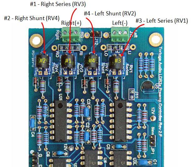
The first step in diagnosing and replacing a bad LDR is to familiarize yourself with the identity and location of each of the four attenuation LDRs on the particular model of preamp controller board present in your preamp. There are currently 2 different models of preamp controller board that uses replaceable plug-in LDR modules; the V2 and the V25. These are both discussed below.
The following table is helpful in identifying the 4 LDRs used in volume control that are subject to the calibration process. The calibration sequence is always #1 through #4. The V2 and V25 boards differ slightly in the physical locations of each of these LDRs.
| LDR Function | Calibration Sequence | V2 ONLY Circuit Board Label | V25 ONLY Circuit Board Label |
|---|---|---|---|
Right Series |
#1 |
RV3 |
RVRSE |
Right Shunt |
#2 |
RV4 |
RVRSH |
Left Series |
#3 |
RV1 |
RVLSE |
Left Shunt |
#4 |
RV2 |
RVLSH |
The V2 and V25 preamp controller boards are shown below with each of the 4 LDRs identified. The above table cross-references the various ways of identifying each LDR.
It is most useful to identify the LDRs in terms of their calibration sequence (#1 through #4) since this sequence is shown on the preamp display during the calibration process.
V25 preamp controller
During calibration, a V25 preamp controller with dual 7-segment displays will show the LDR # in the left display and the calibration step # in the right display. A V25 goes through steps 1-99 for each LDR.
A V25 preamp controller with and OLED display offers considerably more status information during the calibration process. Each of the 4 LDRs goes through a 3 phase calibration process referred to as VLo, VRef, and Cal. Each of the 4 LDRs first goes through the brief VLo phase. Then, starting again with LDR #1, each LDR goes through a brief VRef phase immediately followed by the main Cal phase. The Cal phase will take several minutes going 100 individual calibration steps for each LDR.
When a specific LDR (1, 2, 3 or 4) goes sufficiently out of spec, the calibration process in the V25 is most likely to fail to progress through either the VLo or VRef phase. Less common is for the V25 calibration cycle to stall out somewhere in between step 1 and step 99.
Note that the V25 also uses LDRs for input channel switching and also for isolating the output signal during calibration. Those LDRs are identified below but are on/off only and are not involved in the calibration process.
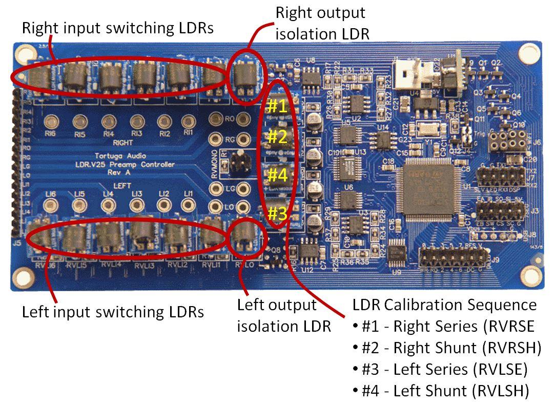
V2 preamp controller
During calibration, a V2 preamp controller with dual displays will show the LDR # in the left display and the calibration step # in the right display. A V2 goes through steps 1-70 for each LDR.
When a specific LDR (1, 2, 3 or 4) goes sufficiently out of spec, the V2 will have a difficult time starting or completing the 70 step calibration sequence for that LDR. The calibration process may stall out at step 1, step 70, or at some intermediate step between 1 and 70. When this happens, note the LDR # in the left display. This usually indicates the LDR needs to be replaced.
4.7. Replacing A Bad LDR
To replace an LDR first remove power from the preamp. Then simply remove (unplug) the suspected bad LDR (the one at which calibration stopped progressing) and replace it with a new LDR Module.
IMPORTANT! - When installing a new LDR module make sure that the white dot on the LDR module circuit board is on the same side as the white dot on the controller circuit board. The LDR modules are NOT keyed so it’s possible to plug the module in 4 different ways but only 1 is the correct way.
After a new LDR module is installed, you should immediately run the unit through a cycle of calibration. This will rebuild the attenuation table for your current impedance setting/level and in doing so will measure and incorporate the unique performance curve of the new LDR module.
LDRs operate as pairs of Series & Shunt resistors with one pair for the Right channel and the other pair for the Left channel. If, after replacing a faulty LDR, the calibration process still slows down or halts at the same LDR as before, it’s likely that it’s companion LDR is the cause of the problem. In this case, remove the new LDR and put the old LDR back. If calibration stopped at LDR #1, replace LDR #2 instead. If calibration stopped at LDR #2, replace LDR #1 instead. If calibration stopped at LDR #3, replace LDR #4 instead. If calibration stopped at LDR #4, replace LDR #3 instead. Then run calibration again. Chances are good that calibration will now run to completion normally. In rare cases you may find you have to replace both the Series and Shunt LDR Module for a given channel in order for calibration to work properly.
4.8. Special Considerations For Balanced Preamps
Balanced preamps utilize 2 preamp controller boards. When facing the front of the preamp looking towards the rear of the preamp, the rightmost controller board is designated as the primary (master) and the left board is designated as the secondary (slave). All user control inputs are handled by the primary board which in turns controls the secondary board.
For purposes of diagnosing LDR replacement in balanced preamps, it’s best to view the left/right channel labels on each controller boards as NOT necessarily being synonymous with the Left and Right stereo channels and simply think of them as LDRs #1 through #4 in terms of their calibration sequence.