ePot.V3 Max Electronic Stepped Attenuator
Price: $249
This is a legacy product and is no longer produced or sold by Tortuga Audio.
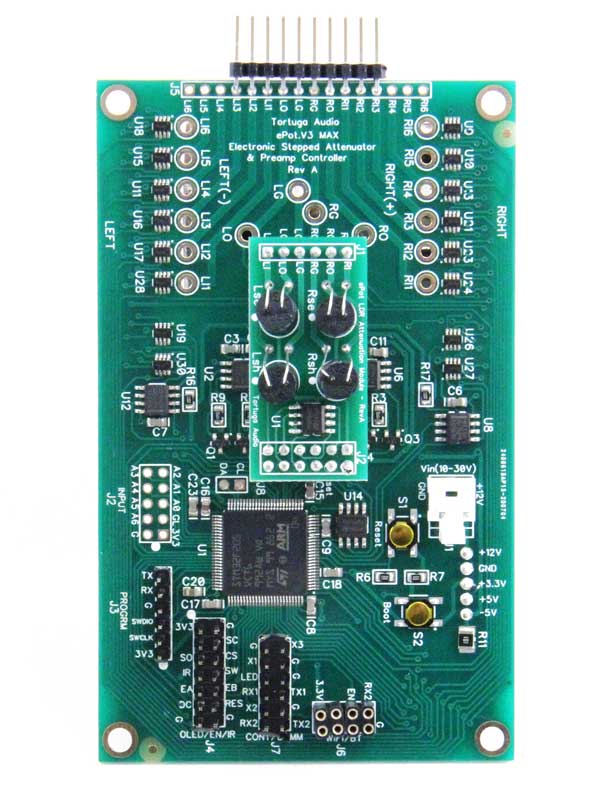
The ePot.V3 Max ("V3 Max" or "Max") is a chassis-mounted electronic stepped attenuator and preamp controller board for the DIYer, designer, or OEM. It provides 2-channel, 100-step stereo volume control, input switching for up to 6 sources, remote control, and an optional (highly recommended) high-contrast OLED display with a menu-driven interactive interface.
The V3 Max is an analog volume control device run by a software-driven 32-bit ARM microcontroller — audio signals are not manipulated in the digital domain, and are optically isolated from any power source. There’s no active gain stage and no active output/buffer stage; each audio signal sees only 2 resistors (LDRs) that control volume by reducing the incoming signal’s voltage. By itself, the Max can be used as a passive preamp; mated to a downstream gain and/or buffer stage, it becomes the attenuator/controller of a high performance active preamp.
The Max is the successor to Tortuga Audio’s V25 preamp controller, and represents the company’s 5th generation of LDR-based audio attenuation technology.
V3 Max Rev C design update — October 2021 release
Rev C eliminated the separate piggy-back power board, moving all components onto a single board for a more stable, robust product with even better sonic performance.
Version |
Rev A |
Rev B |
Rev C |
Release date |
Sept 2020 |
May 2021 |
1Q 2022 |
DC-DC power board |
Design by Texas Instruments |
Simpler, more robust, more efficient, quieter design by Tortuga Audio |
Same design as Rev B, but power board eliminated and parts moved onto the main board |
Minimum load resistor |
Negative 5V minimum load resistor for stability |
Deleted, no longer required |
Same as Rev B |
3.3V power capacitor |
Small, ceramic |
Added larger electrolytic storage capacitor for stable supply during transients |
Same as Rev B |
Mono mode |
Yes |
No — mono mode switch removed to eliminate any possibility of channel cross-talk |
Same as Rev B |
Part changes |
Baseline |
Removed U31 & R11; relocated S1, S2, R6 & R7; added C13; replaced power board (underside of main board) |
Deleted the S1/S2 boot/reset switches |
Key features
-
LDR attenuation module: 100-step attenuator, -60 to 0 dB, adjustable impedance 1k-100k (20k default), integrated LDR calibration (no LDR matching required), plug-in replaceable attenuation module
-
Input switching between 6 stereo sources
-
Smooth stepping with no sonic artifacts; no mechanical switches in the signal path
-
Remote controlled (Apple infrared remote); manual control via rotary encoder with integral push button
-
Smooth muting/unmuting; left/right channel balance with reset (+/- 10 dB)
-
Optional status LED
-
Optional high-contrast 256x64 pixel menu-driven OLED display with encoder & IR receiver
-
Compact — 2.9" wide x 4.4" long x 1.2" deep; chassis mounted with standoffs
-
Serial (UART) and TTL communication & control interfaces for customization
-
100 MHz ARM microcontroller, programmed in object-oriented C++
What’s included?
-
ePot.V3 Max board with attached triple-voltage power supply board
-
IR receiver module with 6" 3-wire square pin connector cable
-
Status LED with 6" 2-wire square pin connector cable
-
Power connector plug with crimp pins
The Max can also be purchased "bare" without an attenuation module, at reduced cost, provided an existing LDR or discrete attenuation module is on hand — an attenuation module is required for the Max to function.
Optional (but recommended) items
-
OLED display assembly — the V3 Max is engineered to work optimally with this visual display; includes IR receiver, encoder, and cables.
-
Encoder — for manual control and pairing the Apple remote; included as part of the OLED display.
-
Apple remote — required for remote control.
What’s not included
-
A nominal 12 VDC power supply — the V3 can run from any DC voltage 9-30 VDC, drawing no more than 0.3A (with OLED display)
-
The optional items above
-
Audio signal input/output jacks
-
Preamp enclosure
LDR attenuation module
The V3 LDR Attenuation Module mounts all 4 LDRs together on a single board with an EEPROM chip that holds the impedance and attenuation data unique to that set of LDRs. It plugs directly into either ePot.V3 model, providing 100 attenuation steps of ~0.6 dB/step over a -60 to 0 dB range. Since LDRs are true analog devices, transitions between steps are smoothly continuous — no audible stepping artifacts.
Improved LDR control & calibration
The ePot.V3 replaced voltage control of the LDR’s internal LED with precision closed-loop current control, decoupling LDR performance from power supply voltage levels for more predictable, stable, repeatable behavior. It also introduced an improved calibration system — a simpler yet more precise 16-bit approach, replacing the previous 12-bit system — built into the ePot.V3 Max.
Visual feedback & display options
The ePot.V3 operates without any visual feedback if needed: an optional status LED indicates on/off status and flashes to acknowledge remote input. Full control functionality and visual feedback requires the graphical OLED display and an Apple remote, together with the Max’s built-in encoder.
Specifications
Attenuator/preamp type |
Passive electronic stepped attenuator & preamp controller. No active manipulation of the audio signal by any power supply; audio signal optically isolated from the control system. |
Attenuation module |
Operates interchangeably with a plug-in LDR Attenuation Module (100 steps of 0.6 dB over 0 to 60 dB, plus 1 muting step) or a plug-in Discrete Resistor Attenuation Module (127 steps of 0.5 dB over 0 to -63.5 dB, plus 1 muting step, fixed 60k input impedance). |
Gain |
Unity (1x) gain — no amplification |
Buffering |
No active or passive input or output stage buffering or coupling |
Input impedance |
LDR module: 20k by default, up to 9 additional configurable settings between 1k and 99k. Discrete module: fixed 60k. |
LDR calibration |
Integrated offline LDR module measurement and calibration against 100 attenuation resistance values, results stored on the plug-in LDR module’s EEPROM. User-initiated, or configurable for periodic automatic operation when otherwise off. Changing input impedance requires a new calibration cycle at that value. |
Number of channels |
2 independent channels (stereo) |
Channel balance accuracy |
Within 0.5 dB over the full attenuation range |
Audio signal ground |
No connection of signal grounds to power ground within the controller; audio signal ground must share a common ground with the power supply via an external star ground point for self-calibration to function properly. |
Audio inputs — single-ended |
1 board accommodates up to 6 switchable single-ended stereo inputs. |
Audio inputs — balanced |
2 boards accommodate up to 6 switchable balanced stereo inputs (and can mix single-ended and balanced). |
Audio input switching/isolation |
Via analog switches — typical 2 ohm resistance when on, in excess of 10 megaohms when off; no mechanical relays in the signal path. |
Audio output switching/isolation |
Attenuation LDRs minimize output during muting; analog switches isolate output during calibration. |
Total harmonic distortion |
LDR module: typically less than 0.5%. Discrete module: typically less than 0.1%. |
Power input |
7-30 volts DC rated at 0.5A via J1 |
Power regulation |
2-stage DC-DC regulation — switching regulation followed by linear regulation for 3.3V digital power and split voltage +/-4.5-5V for analog power |
Processor |
ARM STM32F2 32-bit microcontroller running at 100 MHz |
Control input — remote |
Silver Apple infrared remote or equivalent (38 kHz NEC protocol, Apple commands), via an IR receiver module attached indirectly via the display module or directly to board pins |
Control input — encoder |
Rotary stepped encoder with integral push-button switch, attached via the display or directly to board pins |
Control input — UART |
Accepts control from an external device via UART serial protocol and specific command codes (available on request) |
Display — OLED |
Graphic OLED with intuitive menu-based control; connects via the J4 header, requires a display jumper across J7.DISP pins |
Display — 7-segment (legacy) |
The original dual 2-digit numerical 7-segment LED display can connect via individual J4 pins, though overall functionality isn’t guaranteed |
Display — status LED |
Connects to the board via J7 |
Mono mode |
Rev A: output switchable between stereo and mono via LDR switch (single-ended audio only). Rev B onward: no mono mode. |
Firmware |
Custom object-oriented C++ code |
Firmware update |
Via a chip-resident bootloader communicating with an external PC application, over a USB-to-Serial (FTDI USB-UART) connection (FTDI interface sold separately) |
WiFi module |
Future ability to plug in a WiFi module via J6 for smartphone app control |
Printed circuit board |
High quality nickel immersion gold pads with green solder mask |
Power draw |
Single board w/ OLED display: 130 mA. Dual boards (balanced or dual mono) w/ single OLED display: 210 mA. Supply voltage 9-30 VDC. |